Pentium 3 or Later Motherboard.
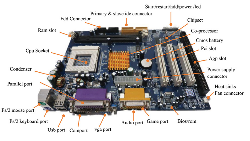
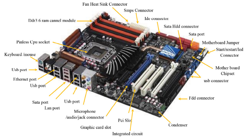
Today’s environment Motherboard.
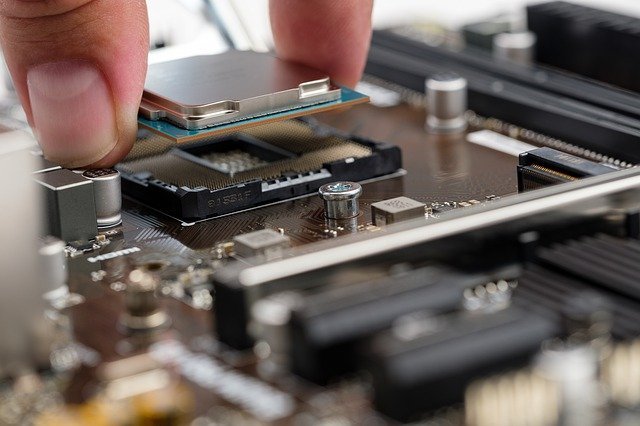
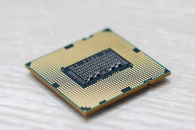
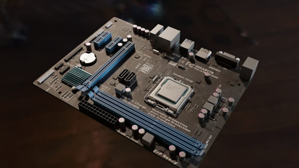
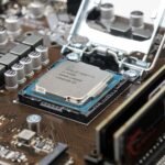
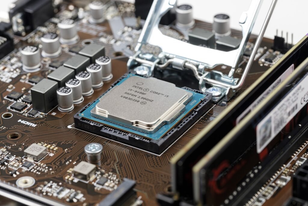
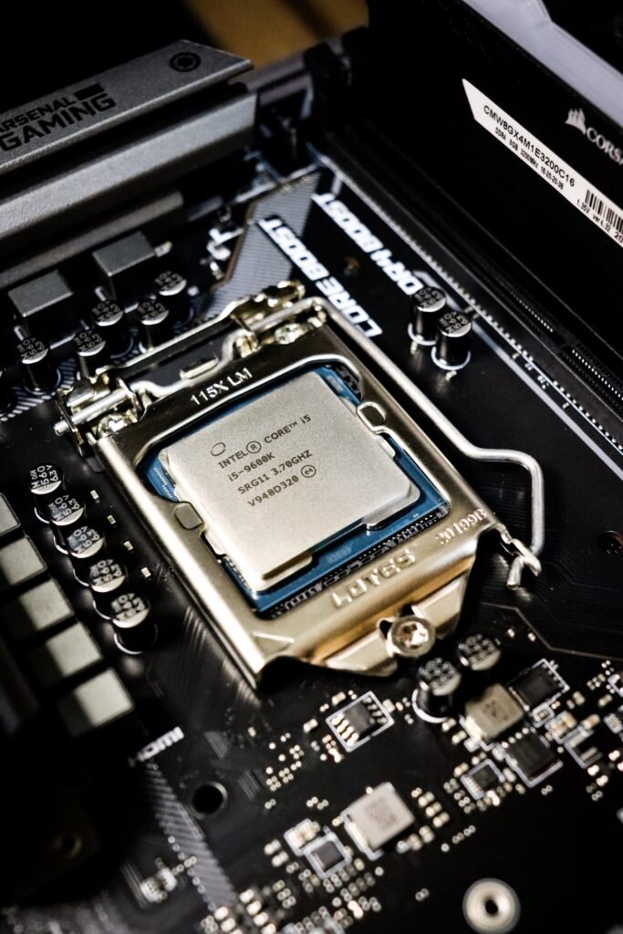
Microprocessor cpu socket – the microprocessor or cpu is the main data and information component in a computer. where it is never easy to do all computer processing without cpu sockets and cpus. where every computer motherboard has a microprocessor installed in the cpu socket. you can barely insert the cpu processor into the pga (pin grid array) 370 p3 socket hole in the p4 or lga (land grid array) 1156 pinless cpu socket in the microprocessor according to the properly installed notch orientation. huh. now you do not install the cpu socket lever until the processor proper to be installed. unless it’s an absolute zero orientation. where the cpu socket forms the connection between the microprocessor and other motherboard components. now you turn on your computer and open the bios menu and see the details of the processor installed and confirm the installation of the microprocessor. here if any problem occurred during cpu socket installation. or you can manually checklist all the procedures to be followed during microprocessor installation. if all is well, and the installed processor information is showing in the bios. so your microprocessor installation is done properly.
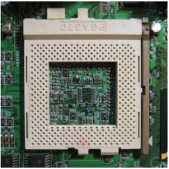
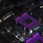
Pin (pga) cpu socket – pga (pin grid array) microprocessor was developed and designed by intel company in the year 1998. where the pentium 3 or pentium 4 microprocessor sockets were the default installed in the pga cpu socket on the computer motherboard. generally, here you need to push the processor pin into the pga socket with a little bit of force. the processor to be installed is pressed from all sides with proper pressure from each notch. now you will press it until it is installed properly. now pull the pga370 cpu socket lever down from the 90-degree to 0-degree insertion force orientation. now here you drop or spread some or a small amount of heat sink liquid onto the heat sink fan with the cpu aluminum heat sink installed on the microprocessor. here it maintains your installed cpu cooling temperature or provides coolness to the cpu when it works for a long time. it even controls the cpu temperature and voltage level. finally, you start your computer, now look for the processor information in the bios menu. if all the information is correct, and the cpu is displayed. so that means, all your steps are correct during cpu installation. where today’s companies have stopped production of pentium 3 pga type sockets. here it is completely replaced with a new lga1156 socket used in intel core i3, i5, i7 processors and the modern newly designed microprocessor cpu socket motherboard.
Pinless (lga) cpu socket – pinless microprocessor socket was invented by intel company. and the new generation intel motherboard is designed with zero insertion force features for lga (land grid array) cpu sockets. where in pga 370 pentium socket you needed to do a manual install with the hard pressing of the cpu. until it is completely properly mounted in the cpu socket. but in lga775 and other pin-less cpu sockets, you don’t need to press hard cpu. here now you just take the microprocessor in hand and carefully place or install it in the lga cpu socket. now pull down on the cpu socket level lever until it connects appropriately to the switch on the bottom. here you install the heat sink, connect a heat sink connector with the supply unit, and you wait for the bios menu to open and view the microprocessor information. see here your current installed processor’s mhz/ghz, frequency confirmation, etc. if everything goes well, it means that the microprocessor is installed correctly in your computer, laptop, desktop.
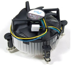
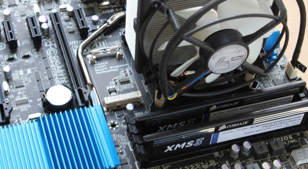
Cpu fan – the cpu fan cools down your current cpu temperature or maintains cpu temperature and humidity during heavy work. when the cpu is working. where the cpu fan is mounted on the microprocessor, where it maintains the cpu temperature voltage level. and prevents the cpu from overheating during processing. if the microprocessor fan will not work or heat sink liquid is not installed on the processor. so the cpu temperature exceeds the normal temperature, in which case your microprocessor will burn out and stop working. here the cpu fan continuously supplies air to the cpu component installed below. where a computer has one or more cpu fans or other fans for graphics card fans, cabinet rear fans, smps fans, etc. all of these are designed to keep hot air out of cabinet appliances and enhance device performance. where each cpu fan has an aluminum heatsink with the cpu fan along with the power unit connector. for improved microprocessor life and performance, remember cpu heat sink fan must be running and installed in proper condition. when it stops working, it burns out components of the microprocessor, and puts your computer into halt mode.
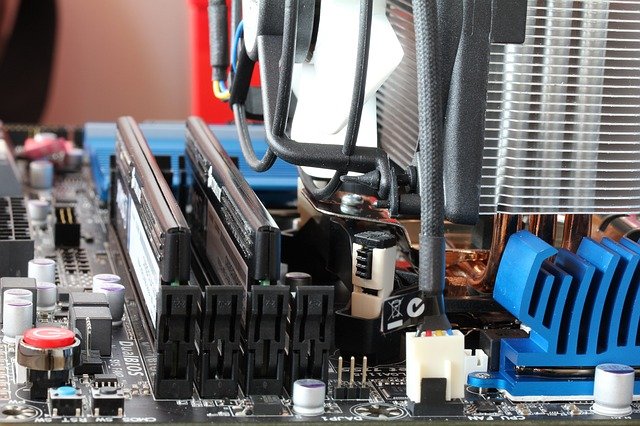
Sim 1 slot – abbreviated as sim (single in-line memory module) slot houses the sd-ram installed. where this type of memory slot is used in sd ram motherboards, which were used in earlier pentium, celeron computers. where these sim slot quantities depend on the computer motherboard manufacturer. here it was probably 2 slots or 4 memory slots found in your motherboard. this type of sim type memory slot was used in the era from the year 1980 to 2000. here the installation of sim memory is very easy for you, you buy sim ram and push it into the sim ram slot as per the given instruction with little push. when the ram is properly installed, the contact notch clips to the sim slot on the motherboard pin. and until the user starts the computer in switch-on mode, the ram automatically starts working properly. and you can check active ram installation information in the bios menu.

Dimm1 slot – dimm1 slot is the new motherboard ram slot used to fit or install the new generation memory called ddr ram. where the dimm slot increases the speed of the installed memory device. here the sim slot produces greater compatibility and storage capacity as compared to ram. where dim stands for dual inline memory module type, this type of ram is more commonly used in today’s environment in personal and business computers. even when the computer and other components exchange information with it. so the dimm slot performing ram in dual operation leads to better data and information exchange with both parties.
Fdd connector – abbreviated as fdd connector (floppy disk drive) connector. where it used to be more installed by the motherboard manufacturer company earlier. here you easily connect the fdd connector to the fdd cable to the floppy drive device. where floppy drive devices were more commonly used to copy-paste 3.5” floppy object contents read-write. now the floppy drive is a completely outdated storage media device, and it has been replaced by a smart card or pen drive. but 20 years ago the floppy was a reliable portable secondary storage media device. which allowed data and information transfer portability between multiple computers. where a hard disk or cd rom, dvd rom, an fdd cable is used, similar to an ied cable. where it transfers data and information between the installed floppy disk drive and the motherboard floppy connector.
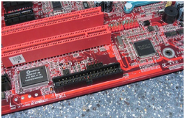
Atx 1 connector – the atx 1 connector allows a computer hardware engineer to connect power supply connectors called smps to a computer motherboard. even this type of atx connector has at least 24 pins of the power connector used in pentium 2 to pentium 3 generation computers. where it allows connecting smps 24 pin power connectors. and the computer motherboard supplies power to the further components of the hardware devices. in today’s modern-day these types of atx connectors have been completely replaced with modern atx power connectors.

Ide cable mother board connector – the ide slot is installed on the computer motherboard. where this type of ide slot was more commonly used on computer motherboards of the pentium generation of computers. where it depends on your computer motherboard manufacturer, it can be in the size of one or two or maybe more. where these slots directly allow computer users to connect hard disks that are connected to the computer motherboard. here before installing the ide hdd drive, you should know about its function and structure in advance, ide slot has a middle notch, which indicates to the ide cable installer how to connect ide cable without any error how to install properly. even these ide slots are used to carry or transfer computer-generated instruction between computer hardware or hard disk drives.
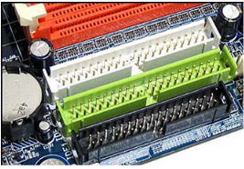
Cmos clear – the cmos clearing method allows a computer hardware engineer or general computer user to revert a computer motherboard to factory settings. where it discards any or all manual changes made by the user to the users. where cmos clear is better for system performance, it removes hardware errors, hardware compatibility issues, and related issues. here cmos battery stores information entered manually by the computer user. when you clean it, it moves all system functions to factory mode, and restores the system back to factory mode. it is also a better choice for any personal computer troubleshooting when some common or serious error problems occur in your computer, desktop, laptop. you should avoid clearing cmos on the motherboard if you have no special computer experience.
How to clear cmos.
- Bios menu.
- Cmos battery.
- Jumper Settings.
Bios menu – here you can launch the computer bios menu by pressing del, f10, f2, keyboard keys to enter the bios menu in your computer. now you can select load setup default or customize setup default option. here you get different bios options in different bios manufacturer companies. like, amiibos, phoenix, award bios, etc. now here you can modify or revoke all the manually added user changes. by applying this menu, the system discards all manual changes. and the system is restored to the previous original motherboard state. here we can compare motherboard bios with computer nervous system. this means that, each computer hardware motherboard function is easy to control and manage through system bios settings in case the user would need to modify it manually. but be strict or be careful while changing the setting of bios. do not modify each of these settings and do not control that setting. with which you are not well acquainted. because it can cause a serious error in system performance during a normal program.

Cmos battery – the cmos battery is a small design battery cell. which manually stores all the bios information in it. where the cmos battery stores information in the battery or cell and retrieves it, cmos consumes the power by the cell. when you remove the cmos battery cell, it immediately releases the bios settings and information stored in it. it even takes back the bios settings in factory setting mode. now restart your bios, and reconfigure the bios settings required for proper system booting. when you unplug the cmos battery, it restarts all cmos functions in default mode. here you apply this process carefully. if you have less skill it’s because these settings stop configuring your services and settings manually. and your motherboard system settings return the system to factory settings mode.
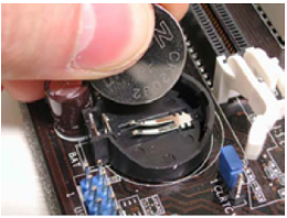
Jumper setting – the jumper setting stores the cmo information protected in the bios. where the default jumper is set to 1 and 2 when you place them on 2 or 3 jumper pins. so it releases and destroys all the information cmos stores. where the jumper is located on each motherboard. when you open the computer cabinet case carefully, and pin it into place on pins 2 and 3. again you restart your computer machine and put it in default location set it on jumper 1 and 2 pin location. then the jumper also takes you to the factory settings in the basic properties of the motherboard.
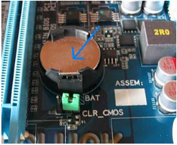
Sata port – abbreviated as pata (parallel advanced technology attachment) for the new generation motherboard port replacement (serial advanced technology attachment). where pentium 3 or pentium 4 is the pata port used in celeron motherboards. but nowadays sata port connection is common for cd rom, dvd rom, hard disk, and other sata enabled secondary storage media devices connection connectivity. where the sata port carries the information between the connected optical device, the hard disk, and the motherboard components. here ide port comes in 40 pins or 80 pins pata connector. these ports also carry information between ide hard disks, as the sata port comes in a 7 pin port. now plug the sata cable into the sata hard drive and connect the other end cable properly to the plug-in motherboard sata connector. where the sata port reduces the amount of cable, free space, and faster data speeds between the motherboard and computer components.

Panel/connector – the motherboard panel connector is an equipment control location on the motherboard. here the motherboard is in the proper screw location in the cabinet. after system installation, you need to manually connect all motherboard port connectors with smps, sata, optical drives, and important panel connectors. several switches and leds are visible on the flat cabinet panel, outside the front view of the computer cabinet. where it plugs all the cabinet panels into the motherboard panel connector. these connect start, restart, hdd led, cd/dvd rom led, power led, speaker, button connect and function properly to the motherboard panel components.
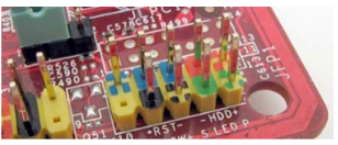
Briefly explain the front panel connector
Power sw – the power self connector is used to connect the cabinet front cable to the flat panel. where you manually press the external and display mount start button to turn on the computer in display mode.
Reset sw – the reset sw button restarts the personal computer. if an error occurs preventing the system or causing any other kind of error. where the reset button keeps the new o/s copy in the ram in your computer and it skips all the problems in loading the new o/s copy during the computer restart process.
Hdd led – hdd led is a light used for connecting with hdd display during hdd computer processing data and information transfer. when the hdd deals with any process and activity, it continues blinking in red, and indicates the system is in process mode. where does the hdd lead blink or steady mode. when the hard drive is reading, writing, transferring, or processing any information.
Power led – the power (light-emitting diode) used in the cabinet to display the power is in active mode. where if it is on/off or in standby mode. where you press the esc button to take it back from stand mode to normal mode.
Speaker – speaker panel connectors are used to connect internal cabinet connectors with cabinet rear panel multimedia components. where the speaker system produces the sound of the activity beep. when it is in turn-on mode. even the speaker is designed for any troubleshooting errors just to play sound at a smaller size. here it could be the ram beep system. where every computer has one and many series of beeps. which indicates specific system activity.
Usb connector – usb has been abbreviated as the (universal serial bus) standard port, briefly replacing the older lpt and com ports. where the usb port is very small in size, which can connect many modern peripheral devices with the usb port and digitally transfer data and information. it transfers data transmission faster than other system ports. where we can easily connect a mouse, pointing device, keyboard, card reader, printer, usb hdd, pen drive, smart card, audio/video player, camera, digital camera, scanner, projector, and other remaining usb supported devices to computer, desktop, the laptop can be connected to the usb port. , even we can connect up to 127 devices with a single usb port. here you configure each one of the usb ports manually. all usb ports are designed as plug-and-play devices. where some devices do not require a usb port to install the software. and some system hardware refers to manually installing software for better system device working performance. here the plug cable into a single motherboard and one or more usb connectors in the front and rear usb port connections for the device, and use it.
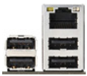
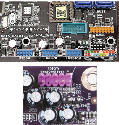
Audio Connector.
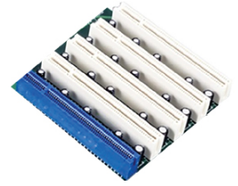
Pci slot – the pci slot is an important slot in a computer motherboard. where it is used is when you need to install additional vga cards, sound cards, printer cards, modems, network adapter nics, graphic cards, tv tuner cards, and many other remaining cards to easily fit into the pcie slot. is required. where pci stands for (peripheral component interconnect). even the pcie slot multiplies the capacity of the motherboard. whenever you want to install new technology or card pci slot. so allows you to easily install them on the pcie slot.
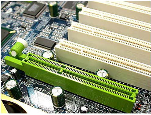
Agp slot – abbreviated as agp (accelerator graphic port) also called agp slot. where the agp card is fitted into the graphics card slot on the agp slot. which accelerates or exceeds the speed of graphics video cards and 3d animation playing game software. by default, some motherboards have a video graphics card inbuilt, and some require it to be manually installed on the agp slot. where you can buy any company’s video card. now open your cabinet system case and easily push the agp card into the agp slot. where today’s company does not make agp slots. because the motherboard manufacturer got a large number of graphics video cards built-in in a newer version. which makes graphics applications and advanced 3d gaming features more efficient and smoother for your machine.
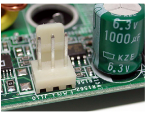
System fan – the system fan connector is installed on the computer motherboard. where it connects the cpu cooling fan to the motherboard connector. where if the cpu fan is installed properly, you now plug the cpu fan heat sink connector into contact with the motherboard system fan connector. where it removes heat or hot air from the microprocessor, and maintains a constant cooling level of the system. typically, the motherboard provides two system fan connectors, one reserved for the microprocessor, and the other one used to remove heat from the computer case. which is called the rear fan connector. it even requires you to install more than one computer cooling fan. because they control the cabinet environment, and maintain the state of the system cooling level.
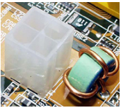
Atx – the atx 4 pin motherboard connector provides power to the motherboard components. where it generates +12 volts default to the microprocessor voltage. where the 4 pin atx connector is specifically designed to provide additional electric power directly into the cpu. here are two common pairs of wires used by atx power cable connector 2 black and 2 yellow wire for motherboard socket.





















Thanks for sharing. I read many of your blog posts, cool, your blog is very good. https://accounts.binance.com/vi/register?ref=OMM3XK51
Everything is very open with a very clear explanation of the issues. It was really informative. Your website is extremely helpful. Thanks for sharing!